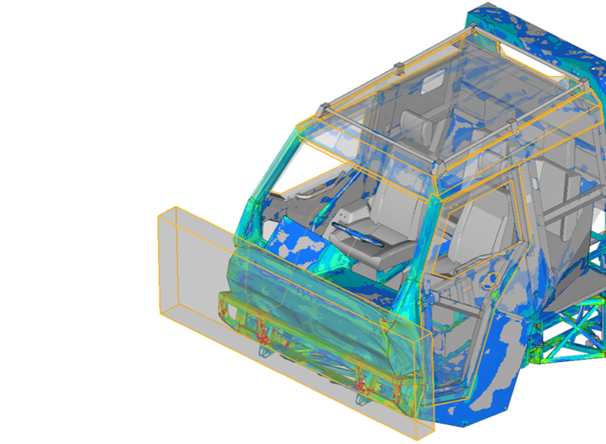
Explicit dynamics can represent evolving contact, large deformation, material failure and rapidly changing load paths without global equilibrium iterations at each time step. Reliable engineering conclusions also depend on appropriate material representation, numerical controls and verification of the transient response.
1. Preserve the important physics
An explicit model must represent the relevant loading timescale, initial conditions, mass distribution, structural stiffness, boundary conditions and applied loads. This is particularly important for impact and blast events, where inertia, shock-wave propagation and stress-wave propagation can govern the response.
Computationally demanding simulations can be made more efficient through appropriate mesh design and numerical controls, including selective mass scaling. Where contact stiffness restricts the time step, carefully justified adjustments to its numerical treatment may also help. These should not be confused with arbitrarily changing the physical stiffness of the structure.
Adjustments to mass, stiffness or loading duration must be assessed for their influence on inertia, wave propagation, rate-dependent material behaviour and the predicted structural response.
2. Mesh quality and fidelity influence accuracy and time-step control
For many explicit structural elements, the critical time step can be estimated from the element's characteristic length divided by the material wave speed. The characteristic length depends on geometry and element formulation, while wave speed depends on effective material stiffness and density.
For a homogeneous material with comparable element formulations and material states, the smallest characteristic length will typically impose the most restrictive element time step. In a multi-material model, a larger element with a higher material wave speed may instead govern. Contact stiffness and other solver controls can also affect the time step used by the model.
The model’s mesh must therefore balance the resolution needed to capture stress gradients, contact geometry and structural deformation against computational cost.
Significant distortion during loading can reduce characteristic lengths and affect the stable time step. Reviewing how the mesh deforms is therefore as important as checking its initial quality.
3. Review contact definitions and response
Many explicit problems are contact dominated. Initial gaps or penetrations, contact stiffness, friction, edge treatment and the representation of component thickness can materially affect force histories and deformation modes.
Review contact-force histories alongside the animation, checking penetration, separation and sliding behaviour. Unexpected force spikes or abrupt changes in contact state should be investigated to distinguish physical events from numerical artefacts.
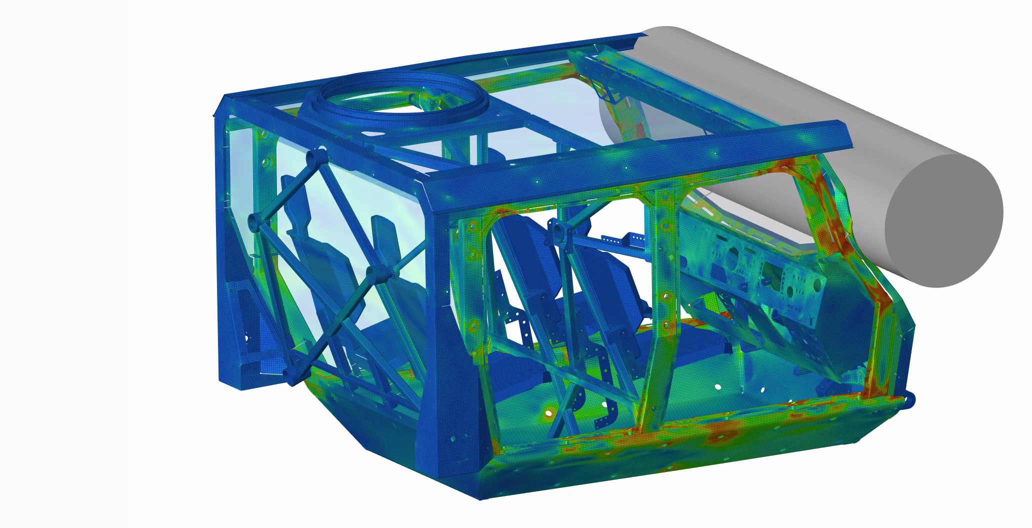 Cab impact simulation showing structural deformation and load transfer under pillar impact loading.
4. Assess time-step control and mass scaling
Mass scaling can increase the stable time step, particularly when a small number of elements restricts the entire model. However, changing mass also changes inertia. The amount, location and timing of added mass should therefore be assessed, rather than relying solely on the percentage increase in total model mass.
Where scaling could influence the conclusions, compare key results with a less aggressively scaled or unscaled model.
5. Monitor the energy balance
Energy histories help establish whether the physical and numerical behaviour is consistent with the intended event. Review kinetic and internal energy alongside the initial energy, external work and relevant dissipation or numerical energy terms. Interpret each output according to the solver's definitions: frictional dissipation, contact-penalty work and artificial stabilisation energy are not interchangeable quantities.
Beware of hourglass energy!
Hourglassing is a non-physical deformation mode that can occur in reduced-integration elements when particular distortions are not detected by the integration scheme and therefore generate no corresponding strain energy. Hourglass controls suppress these modes, but their numerical contributions should be reviewed alongside the deformation pattern. Check critical regions as well as global energy totals; a low global contribution can conceal a local problem.
In a deforming crash structure, substantial conversion of kinetic energy into internal energy is expected. For quasi-static explicit assessments, kinetic energy associated with the deforming structure should generally remain small relative to its internal energy through most of the loading. Interpret this alongside reaction forces and deformation, accounting separately for rigid-body motion and any significant transient events.
6. Verify the response
Check both the numerical solution and its agreement with the intended physical behaviour.
Useful checks include:
- Compare initial kinetic and internal energies with expected values, and monitor their evolution alongside external work and other relevant energy terms.
- Animate the model's deformation, examine contact behaviour and interrogate contact-force histories.
- Verify component masses, centres of gravity and moments of inertia against the intended physical system.
- Review mesh quality and resolution throughout the model, including sensitivity of key results to refinement where appropriate.
- Conduct time-step, mass-scaling and, for quasi-static assessments, loading-duration sensitivity studies where relevant.
- Compare predictions with physical test data, analytical estimates or recognised benchmark cases, accounting for differences in loading, geometry and boundary conditions.
Numerical verification and comparison with physical measurements provide complementary evidence. Their scope and limitations should be clear in the assessment.
7. Output sufficient data to capture the event
Transient models can generate substantial data volumes, but sparse output may miss important peaks or make a completed run difficult to diagnose. Select output intervals to resolve the force histories, contact changes and deformation sequences relevant to the assessment.
Targeted, closely sampled time histories for forces, accelerations, energies and critical components can complement less frequent whole-model animation output.
The output interval is distinct from the solver's integration time step. Both must be appropriate: frequent output cannot compensate for a numerical solution that has not resolved the response of interest.
From simulation results to defensible engineering conclusions
Explicit analysis can represent a wide range of complex physical phenomena, but reliable engineering conclusions depend on rigorous model verification and appropriate validation.
Documenting these activities, alongside the modelling assumptions, limitations and supporting evidence, provides a traceable basis for interpreting the results and informing engineering decisions.